Spyros G. Leloudas, Technical Director, SGL Engineering focused his presentation on the ‘’Smart use of 3D laser Scanning and inspections by drones’’ during the 2016 SMART4SEA Forum. He explained that 3D Laser Scanning is a tool for collecting large amount of accurate data within a short time; in essence these scanners collect millions of individual point measurements having each point coordinates and color information. The 3D Scanning work can be performed from land with equipment such as Scanners set on tripods or from air using drones, equipped with various sensors including scanners, cameras etc. From the data collected, an array of drawings and detailed information can be produced and presented, such as 3D Solid Model 3D Intelligent Model including 3D Drawings, Sections, Side & Top views, Isometrics etc
From the 3D Laser Scanning that has proven very important in the Metrology Information for the Shipping Industry as well as in other Sectors (Art, Architecture to Industrial purposes and even Crime or Accident Investigation), we acquire valuable information. The 3D Laser Scanning Project is a small puzzle consisting of three pieces:
- 3D Laser Scanning (Field Work)
- 3D Modelling Procedure (Office Work) &
- 3D Intelligent Model (also Office Work
For the first piece of our puzzle we need all the Information for the Project Scope in order to decide for the corresponding HW we shall use in the field work.
The Laser Scanner instrument consists of two parts, the Laser System and the Camera installed on top or inside the Scanner. During Laser Scanning, a laser line is passed over the surface of an object in order to record three -dimensional information. The surface data is captured by a camera sensor mounted in the Laser Scanner which records accurate dense 3D points in space, allowing for very accurate data without ever touching the object.
The 3D Laser Scanning transforms actually anything that can be seen from the position the scanner stands (Setup), into a cloud of points (Point-Cloud) giving co-ordinates to each point, including color information taken by the Camera. However since all the objects those require to be scanned cannot be seen from one location, the Scanner is moved from position to position until the total object is covered. In order to relate and connect the cloud of points (Point-Cloud) taken from each position, bench marks or clearly identifiable control points are used. In between two Scanner Setups a Registration procedure is taking place in order the two Point-Clouds from each Scanner Setup to be included in one and the same Cartesian coordinate system related to the Field or Object Coo.
With the completion of the Field Work the 3D Modeling procedure take place following the steps below:
- Various SW applications are used for 3D Modeling, depending on the object whose three-dimensional model we want to build.
- Selecting the corresponding Point-Cloud of an object (pipe, cylinder, flange, valve etc.) we produce the Solid Item.
- Finalizing the 3D Solid Model of the scanned field we create:
- 3D Drawings, Sections, Side Views, Top & Bottom Views, Isometrics,
- 2D Drawings, Sections, Side Views, Top & Bottom Views, Isometrics,
- Material & Equipment List etc.
The next step of Office Work concerns the data to be included in the finished product: For each 3D Solid Item the following data can inserted:
- Date of Purchase
- Date of Repair
- Date of Service
- Price
- Supplier Info
- Material Info
- TAG Info
- Corresponding System it belongs
- Service Manual
- Technical Manual
- User Guide Manual etc.
All the above steps are establishing the Reverse Engineer Procedure. Various screenshots from the software we are using in order to produce the drawings from the 3D model are followed. Below we can see completely the 3D model of this unit of the refinery here.
We can also see (screenshot 2) that we are selecting this branch in order to implement it with various information that it is required. In addition, we can see all the information from this selecting valve from the 3D model that we got
In screenshot 3, we can see that selecting the pipeline that is colored red, we are directly getting the isometric drawing with all the information that is needed .
In screenshot 4 we got more details of the isometric drawing.
In screenshot 5 we are getting all the information that we need in order to assembly this entire pipeline
Finally, there is another screenshot (in screenshot 6) of an intelligent one line diagram of the P& IDs
The Reverse Engineering is essential in cases where:
- There are not updated drawings
- Retrofitting is required and suitable spaces must be located for the new equipment
- Investigation of possible pipe collisions in retrofitting
- Pipe interconnections required with the existing equipment
- Any Structural collision investigation
- Structural Prefabrication
Inspection by Drones
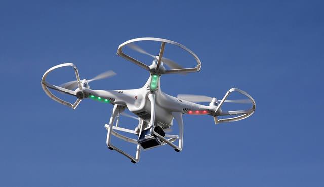
In our case we are interested for the DRONES that can be used as useful equipment for HD Photographing (Photogrammetry), HD Video Capturing, 3D Scanning, Monitoring etc. You can equip a drone with numerous HW equipment such as sensors measuring (temperature, humidity, radiation, noise, pollution etc.), 3D Laser Scanner, HD Video Cameras, HD Photo Cameras and start flying around, taking pictures making videos, scanning anything you can think off, but the case is not like that.
Advantages in computer technology global positioning and miniaturization have conspired to remove considerable barriers to entry to this new era of drones. These advancements enable new practitioners to provide a greater array of services to new and existing markets than ever before and fosters the misconception that “anyone can do it”. But this attitude is on the wrong path. You must know your field before you can proceed to using the DRONE as measuring equipment. The same holds for any work you are prepared to be involved in. You must know first of all your subject in depth before you decide what equipment to use, the equipment are there waiting for you.
However we must not forget that a drone is a flying machine of approximately 25kg with the equipment. It is potentially a dangerous flying object that can cause damages and injuries to people if not used properly. Are there any regulations governing the use of this flying machine? I would say NO. The only Legislation and Regulations in Greece is for flying model aircraft FEK B9 2010 and it does not cover the DRONES. Another serious difficulty is that: “All flights must be insured for property damage and personal injury to third parties” according to FEK B9 2010. However according to ING Insurance Company there is no Legislation enforcing the Insurance companies to insure the Drone flights. Therefore all flights are under the responsibility of the owner and or the users.
Above article is an edited version of Mr. Spyros Leloudas presentation during the 2016 SMART4SEA Forum
Please click here to view his video presentation
The views presented hereabove are only those of the author and not necessarily those of SAFETY4SEA and are for information sharing and discussion purposes only.


