Transport Malta’s MSIU issued a report analyzing the probable causes of Main engine damage onboard the RoRo cargo ship ‘Chodziez’, while en route on a laden voyage from Oran, Algeria, to Marseille, France, on 31 March 2017.
The incident
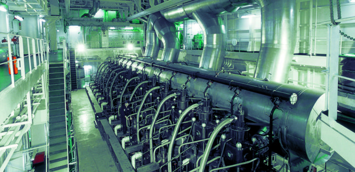
Soon after taking over his watch, the third engineer inspected the machinery running condition from the engine control room. He observed that the main engines’ loads, propellers, revolutions, exhaust gas temperature, lubricating oil and cooling water temperatures and gearbox oil temperatures were normal. After visually inspecting the running machinery, he observed no abnormal conditions, while the oil mist detectors and separators were also working fine.
As per normal procedure, the engine-room visual inspection was carried out every 30 minutes. At about 1457, the third engineer noticed an alarm in the engine control room. A closer look revealed that it was one of the oil mist detectors’ alarm. The alarm, which activated due to a high lubricating oil mist in main engine no. 2 crankcase, was soon followed by a low lubricating oil pressure alarm on the same engine.
Upon noticing these alarms, he pressed the main engine no. 2 emergency stop button and reported the matter to the chief and second engineers. The three engineers waited for 30 minutes in the engine-control room for the main engine to cool down. Following the delay, the crankcase doors on main engine no. 2 were opened for a visual inspection. The extent of the damage was immediately evident. No. 2 main bearing had seized. White metal particles were visible on the crankcase walls. Main bearing shells were noticeably damaged and it was also suspected that the crankshaft’s main journal no. 3, big end bearing no. 2 and the corresponding connecting rod journal were damaged. Bearing shells were displaced and raised from their housing
Probable cause of the oil mist alarm
Oil mists are potentially hazardous conditions inside an engine in view of the created explosive conditions. The presence of an oil mist is the result of oil vaporisation in the crankcase, caused by either a hot spot or an overheated part within the crankcase.
The natural atmosphere inside the crankcase consists of large globules of oil dispersed through the air. A hot spot (with a minimum temperature of about 360 °C) can vaporise these oil globules. The vapour, rising to cooler parts of the crankcase, is then condensed into an oil mist, consisting of small globules of oil of approximately 2-10 nm in diameter. If ignited, an accumulation of this oil mist can cause a heavy explosion.
The safety investigation concluded that the oil mist alarm was triggered by a mist of oil, which was generated by a hot spot, following the failure of the bearing shells.
Probable cause of the shell bearing no.2 failure
Microscopical examination of the bearing surfaces suggested that the failure of the bearings could be broadly attributed to two phenomena:
- big end bearing no. 2: extensive galling initiated by its assembly misalignment; and
- main bearing no. 3: delamination of babbitt material due to reduced adhesion strength and / or fatigue.
It was also considered possible that the delamination of the babbitt material caused the other failure, or at least facilitated its extensive occurrence.
It should be noted that galling is generally not a problem when there is lubrication, unless the lubrication breaks down. Conversely, there is generally an exposure to galling when there is no lubrication and is especially dominant when the tribopair is made of large surfaces sliding past one another. However, for such devices to experience wide-spread galling, out-of-round conditions or errors-inform (i.e., unintended high spots) are necessary since these create local highstresses. A common manifestation of a galling problem is seizure of the mating parts.
Probable cause of the shell bearing no.3 failure
The babbitt material was observed under optical and electron microscopes. Yet again, no foreign material was found embedded in it; instead, a clean separation from the steel backing could be observed. Large areas of the babbitt metal had spalled away from the backing and other areas could be readily lifted off with minimal force. Furthermore, the analysis also showed extrusion of the lining material out of the bearing edges.
In this case, the failure of the overlay was only partly attributable to fatigue. Fatigue damage overlay is usually visible in the form of a continuous network of cracks, followed by partial flaking of the coatings. In this case, the amount of cracks visible in the remaining lining material did not relate well to the large scale delamination observed for this bearing. However, in the case of Al-based linings (such as this one), it was considered possible that any fatigue cracks formed on the surface and spread inside the lining, had reached the steel back via propagation along the bond line between the lining and the steel.
Other safety issues
Although stopping the main engine was by far the best thing to do, the safety investigation had no evidence that the bridge was informed prior to this action. In this respect, although the second main engine would have ensured a degree of propulsion and manoeuvrability, the engineering OOW was not aware as to whether there were navigational hazards in the area that could have compromised the safety of the vessel.
Moreover, there was also no evidence to indicate that the flow of lubricating oil had been increased after the main engine had been stopped. Increasing the flow of oil is necessary to help reduce thermal stresses caused by the stopping of the main engine and to gradually cool down of the failing parts and avoid welding of parts.
Further details may be found herebelow:


